Common parts and part numbers:
Keyboard: V000040140
CPU cooling fan (inside the heatsink): V000042110
North bridge fan: V000040490
AC adapter: PA3290U-2ACA
Battery: PA3382U-1BRS
DVD/CD-RW drives: V000040170, V000040180, V000041800, V000042710
DVD Multi drive - CD and DVD burners: V000040190, V000041810, V000043060
CPU cooling fan (inside the heatsink): V000042110
North bridge fan: V000040490
AC adapter: PA3290U-2ACA
Battery: PA3382U-1BRS
DVD/CD-RW drives: V000040170, V000040180, V000041800, V000042710
DVD Multi drive - CD and DVD burners: V000040190, V000041810, V000043060
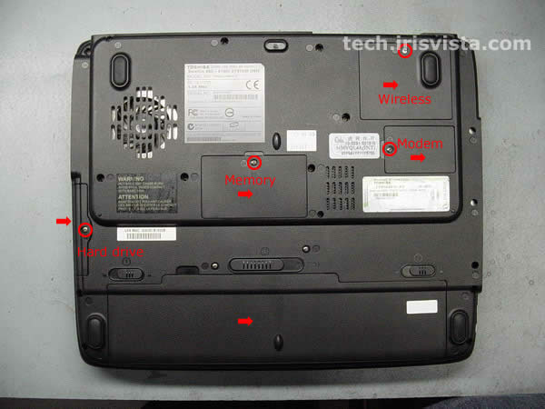 | STEP 1
Turn the unit upside down.
Remove screws securing: the Wi-Fi card cover, the modem card cover, the memory card cover, the hard drive cover. Remove the Wi-Fi card cover, the memory card cover, the modem card cover, the hard drive cover. Remove the battery. |
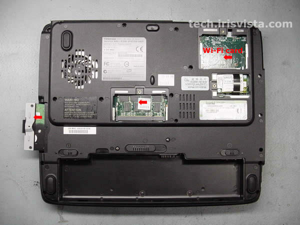 | STEP 2
Remove the hard drive, the memory card, the Wi-Fi card (if you have any).
|
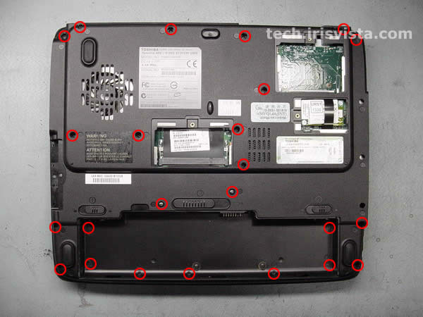 | STEP 3
Remove all screws on the bottom.
Oh,man that's a lot of screws! |
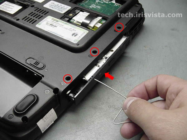 | STEP 4
Open the DVD drive with a paper clip.
Carefully remove the DVD drive from the computer. Remove three screw hidden under the DVD drive. |
 | STEP 5
Turn the computer right side up.
Insert a thin object under the securing strip and lift it up. Be careful, it may be very tight. |
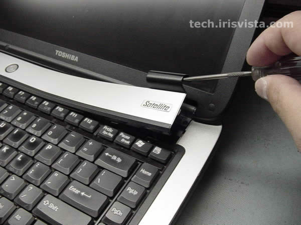
 | STEP 6
Remove the securing strip.
|
 | STEP 7
Remove two screws securing the keyboard.
|
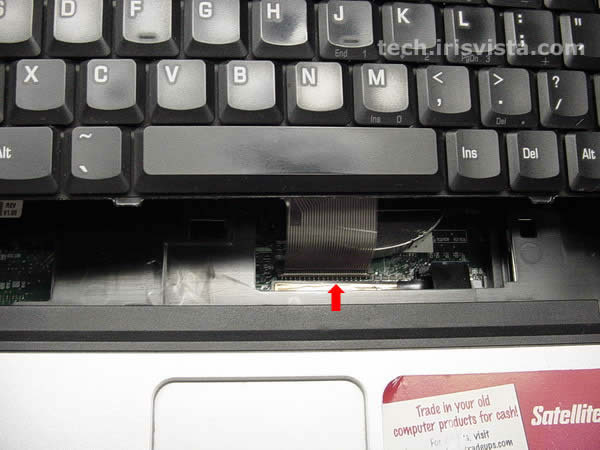 | STEP 8
Disconnect the keyboard cable from the system board and remove the keyboard.
|
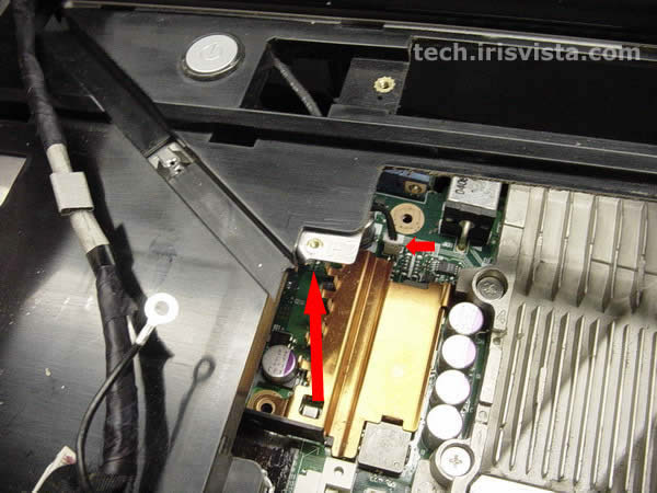
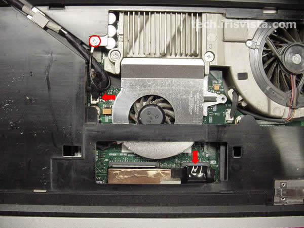 | STEP 9
Disconnect the LCD cable from the system board.
Remove the screw connecting the LCD cable to the base. Disconnect the flat LED board cable from the system board. |
 | STEP 10
Carefully lift the display/top cover assembly off the base.
Do not forget to disconnect the power switch cable from the system board. For some reason I didn't make a better picture :( The display/top cover assembly - LCD assembly and top cover assembly connected by hinges. |
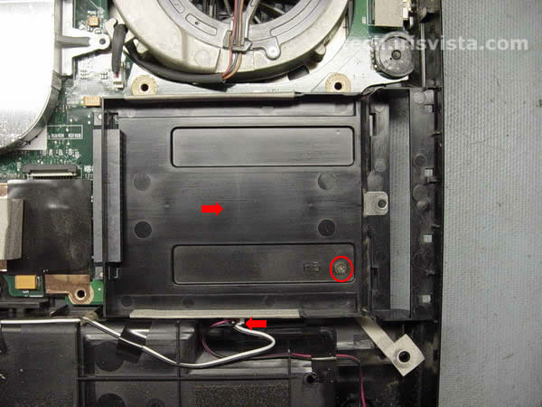 | STEP 11
Remove the screw securing the HDD holder.
Remove the HDD holder. Disconnect the speaker cables from the system board. |
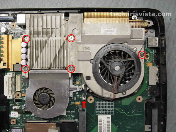 | STEP 12
Loosen five screws securing the heatsink assembly.
Disconnect the fan cable from the system board. |
 | STEP 13
Carefully lift the heatsink off the CPU.
|
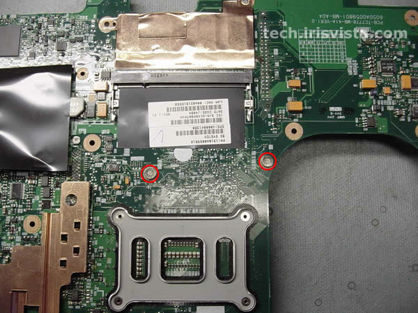
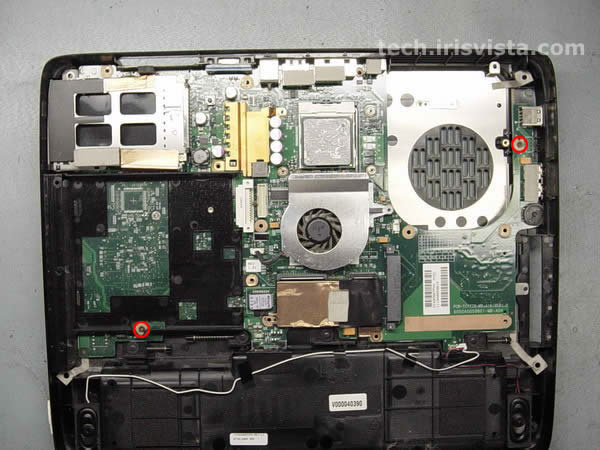 | STEP 14
Remove two screws connecting the system board to the base.
|
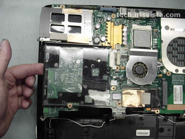 | STEP 15
Starting from the left side carefully lift off the system board.
Be careful with the PC card connector. |
 | STEP 16
Remove the system board off the base.
|
 | STEP 17
Remove two screws securing the modem card.
Disconnect the modem card cable on the system board. Lift the modem and the modem cable off the system board. |
 | STEP 18
Remove the screw securing the optical drive holder.
The screw is hidden under the black tape. |
 | STEP 19
Remove the optical drive holder.
|
 | STEP 20
Remove four screws securing the cardbus connector (PC card connector).
|
 | STEP 21
Turn the system board right side up.
Carefully remove the cardbus connector. |
 | STEP 22
Unlock the CPU and lift it off the system board.
|
 | STEP 23
Turn the system board upside down.
Remove two screws securing the video chip fan. |
 | STEP 24
Remove the fan cable on the system board.
Remove the video chip fan. |
 | STEP 25
DONE!
|
Комментариев нет:
Отправить комментарий